- 您现在的位置:买卖IC网 > Sheet目录337 > LH28F160S3HNS-TV (Sharp Microelectronics)IC FLASH 16MBIT 100NS 56SSOP
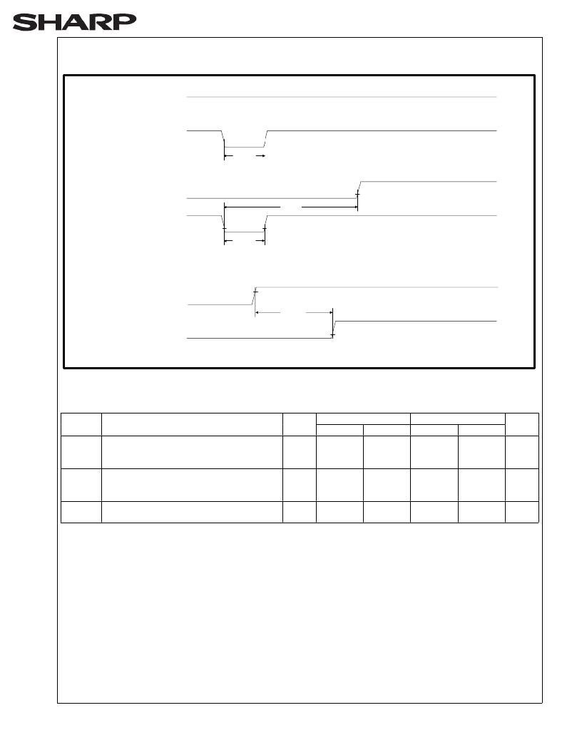
6.2.7 RESET OPERATIONS
High Z
STS(R)
V OL
V IH
RP#(P)
V IL
High Z
STS(R)
V OL
V IH
RP#(P)
V IL
2.7/3.3V
LHF16KTV
t PLPH
(A)Reset During Read Array Mode
t PLRH
t PLPH
(B)Reset During Block Erase, Full Chip Erase, (Multi) Word/Byte Write
or Block Lock-Bit Configuretion
45
V CC
V IL
t 23VPH
V IH
RP#(P)
V IL
(C)V CC Power Up Timing
Figure 21. AC Waveform for Reset Operation
Reset AC Specifications
V CC =2.7V
V CC =3.3V
Symbol
Parameter
Notes
Min.
Max.
Min.
Max.
Unit
t PLPH
RP# Pulse Low Time
(If RP# is tied to V CC , this specification is
not applicable)
100
100
ns
t PLRH
RP# Low to Reset during Block Erase,
Full Chip Erase, (Multi) Word/Byte Write
1,2
21.5
21.1
μs
or Block Lock-Bit Configuration
t 23VPH
V CC at 2.7V to RP# High
V CC at 3.0V to RP# High
3
100
100
ns
NOTES:
1. If RP# is asserted while a block erase, full chip erase, (multi) word/byte write or block lock-bit configuration
operation is not executing, the reset will complete within 100ns.
2. A reset time, t PHQV , is required from the latter of STS going High Z or RP# going high until outputs are valid.
3. When the device power-up, holding RP# low minimum 100ns is required after V CC has been in predefined range
and also has been in stable there.
Rev. 2.0
发布紧急采购,3分钟左右您将得到回复。
相关PDF资料
LH28F160S5HNS-S1
IC FLASH 16MBIT 70NS 56SSOP
LH28F320S3HNS-ZM
IC FLASH 32MBIT 110NS 56SSOP
LH28F320SKTD-ZR
IC FLASH 32MBIT 70NS 48TSOP
LHF00L28
IC FLASH 16MBIT 70NS 48TSOP
LPM409 CHASSIS
STNRD 4SLOT CHASSIS W/INPUT LEAD
LS15RB1201J04
POE SPLITTER 10.8W 12V @0.9A
LT1932ES6#TRMPBF
IC LED DRIVR WHITE BCKLGT TSOT-6
LT1937ES5#TRMPBF
IC LED DRIVR WHITE BCKLGT TSOT-5
相关代理商/技术参数
LH28F160S3HR-L10
制造商:未知厂家 制造商全称:未知厂家 功能描述:x8/x16 Flash EEPROM
LH28F160S3HR-L13
制造商:未知厂家 制造商全称:未知厂家 功能描述:EEPROM|FLASH|1MX16/2MX8|CMOS|TSSOP|56PIN|PLASTIC
LH28F160S3HT-L10
制造商:Sharp Microelectronics Corporation 功能描述:NOR Flash Parallel 3V 16Mbit 2M/1M x 8bit/16bit 100ns 56-Pin TSOP
LH28F160S3HT-L10A
功能描述:IC FLASH 16MBIT 100NS 56TSOP RoHS:否 类别:集成电路 (IC) >> 存储器 系列:- 标准包装:96 系列:- 格式 - 存储器:闪存 存储器类型:FLASH 存储容量:16M(2M x 8,1M x 16) 速度:70ns 接口:并联 电源电压:2.65 V ~ 3.6 V 工作温度:-40°C ~ 85°C 封装/外壳:48-TFSOP(0.724",18.40mm 宽) 供应商设备封装:48-TSOP 包装:托盘
LH28F160S3HT-L13
制造商:未知厂家 制造商全称:未知厂家 功能描述:EEPROM|FLASH|1MX16/2MX8|CMOS|TSSOP|56PIN|PLASTIC
LH28F160S3HT-L75A
制造商:Sharp Microelectronics Corporation 功能描述:
LH28F160S3HT-TF
功能描述:IC FLASH 16MBIT 100NS 56TSOP RoHS:是 类别:集成电路 (IC) >> 存储器 系列:- 标准包装:1 系列:- 格式 - 存储器:RAM 存储器类型:SDRAM 存储容量:256M(8Mx32) 速度:143MHz 接口:并联 电源电压:3 V ~ 3.6 V 工作温度:-40°C ~ 85°C 封装/外壳:90-VFBGA 供应商设备封装:90-VFBGA(8x13) 包装:托盘 其它名称:Q2841869
LH28F160S3-L10
制造商:SHARP 制造商全称:Sharp Electrionic Components 功能描述:16-MBIT(2MBx8/1MBx16) Smart 3 Flash MEMORY
